![]()
Design World - October 2013
Atomic Force Microscope Sees More Through Vibration Isolation
Vibration isolation and better scan size enables atomic force microscopy (AFMs) to see more at the nanoscale level.
Edited by Leslie Langnau - Managing Editor
With its development in 1986, and subsequent commercial introduction in 1989, the atomic force microscope (AFM) is one of the foremost tools for imaging and measuring materials and cells on the nanoscale. Revealing sample details at the atomic level, with resolution on the order of fractions of a nanometer, the AFM is instrumental for imaging an array of applications, such as defining surface characterizations, lithography, datastorage, and manipulation of atoms and nano-sized structures on a variety of surfaces.
The need for more precise vibration isolation with AFM, though, is becoming critical as resolutions continue to bridge from micro to nano. AFM systems are extremely susceptible to vibrations from the environment. When measuring a very few angstroms or nanometers of displacement, an absolutely stable surface must be established for the instrument. Any vibration coupled into the mechanical structure of the instrument will cause vertical and horizontal noise and bring about a reduction in the ability to measure with the highest resolution.
The vertical axis is the most sensitive for AFMs, but these microscopes are also quite sensitive to vibrations in the X and Y axes.
The atomic force microscope uses a sharp tip (probe), with a radius of curvature on the order of nanometers attached to the end of a tiny cantilever used to scan across a sample surface to image its topography and material properties. When the tip is brought into proximity of a sample surface, forces between the tip and the surface lead to a deflection of the cantilever This deflection is typically recorded using a laser beam that is reflected from the top surface of the cantilever to a photosensitive detector. The resultant position change of the cantilever allows characteristics such as mechanical, electrostatic, magnetic, chemical and other forces to be precisely measured by the AFM. These characteristics are displayed in a three-dimensional surface profile of the sample (in the X, Y and Z axes)—an advantage that the AFM can provide compared to other microscopy techniques, such as the scanning electron microscope (SEM) which delivers a two-dimensional image of a sample (in the X and Y axes).
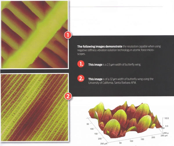
Here is an image of 250 µm width of butterfly wing using University of California, Santa Barbara AFM with negative-stiffness vibration isolation.
Expanding AFM capability and scanning range
Since the release of the first commercial atomic force microscope about 25 years ago, technology advances have improved AFM performance. One of these advances has expanded the AFM ability to image biological samples in an aqueous buffer and provide a range of physical data for the sample. Another has increased the imaging speed of AFMs. Unlike Scanning Electron Microscopes, which are capable of scanning in near real-time, conventional AFMs, prior to about five years ago, required between one and 100 minutes to obtain a high-resolution image. With the introduction of high-speed AFM systems, imaging speeds are three orders of magnitude faster than with previous AFMs.
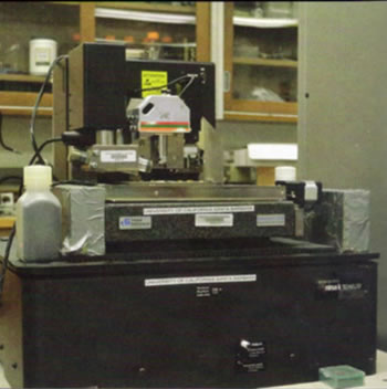 Within the past several years, research into AFM design, conducted In the Paul Hansma Research Group, Department of Physics, at the University of California, Santa Barbara, has demonstrated success with AFM imaging of large-scale samples at nanoscale resolutions while extending the range of the Z-axis.
To image at the extreme depths necessary in large-scale cracks and deep microcracks the AFM must have a Z-range of at least 200 microns and a cantilever tip long enough to probe the crack. As the vertical movement of the tip is increased, however, it brings into play a greater possibility for vibration. This issue was solved with the incorporation of negative-stiffness vibration isolation.
Improving on AFM vibration isolation
Developed and patented by Minus K Technology, negative-stiffness isolators use a completely mechanical concept in low-frequency vibration isolation while achieving a high level of isolation in multiple directions.
In negative-stiffness vibration isolation, vertical-mot ion isolation is provided by a stiff spring that supports a weight load, combined with a negative-stiffness mechanism. The net vertical stiffness is made very low without affecting the static load-supporting capability of the spring. Beam-columns connected in series with the vertical-motion isolator provide horizontal-motion isolation. The beam-column behaves as a spring combined with the negative-stiffness mechanism. The result is a compact passive isolator capable of very low vertical and horizontal natural frequencies and very high internal structural frequencies.
The isolator provides 0.5 Hz* isolation performance vertical, and 0.5 Hz horizontal, using a totally passive mechanical system —no air or electricity required, (*Note that for an isolation system with a 0.5 Hz natural frequency, isolation begins at about 0.7 Hz and improves with increase in the vibration frequency. The natural frequency is more commonly used to describe the system performance.)
"The key factor for us was the incorporation of a true negative spring constant system, together with the positive spring constant, to achieve an effective and very soft spring constant" said Hansma. "This allows the negative-stiffness vibration isolation device to have a very low vibrational frequency in the vertical direction, which is critical for atomic force microscopy."
Negative-stiffness isolators resonate at 0.5 Hz. At this frequency there is almost no energy present. It would be very unusual to find a significant vibration at 0.5 Hz. Vibrations with frequencies above 0.7 Hz (where negative-stiffness isolators begin isolating) are rapidly attenuated with increase in frequency.
"We like the vibration isolation to be at 0.5 Hz, which we can achieve with the negative-stiffness table," continued Hansma. "Not so much because of the vibrations at that frequency, which are minimal, but because 0.5 Hz is 16x more resistant to transmitting vibrations at a building resonance of 10 or 20 Hz, than compared with a resonant frequency of 2 Hz which would be found with air tables."
Air tables, as vibration isolation systems, deliver limited isolation vertically and less isolation horizontally. They can make vibration isolation problems worse since they have a resonant frequency that can match that of floor vibrations. Air tables will amplify rather than reduce vibrations in a typical range of 2 to 7 Hz because of the natural frequencies at which air tables resonate. All isolators will amplify at their resonant frequency, and then they will start isolating. With air tables, any vibrations in that resonant frequency range could not only fail to be attenuated, they could be amplified.
Transmissibility with negative-stiffness isolators is substantially improved over air systems. Transmissibility is a measure of the vibrations that are transmitted through the isolator relative to the input vibrations. The negative-stiffness isolators, when adjusted to 0.5 Hz, achieve 93% isolation efficiency at 2 Hz; 99% at 5 Hz; and 99.7% at 10 Hz.
"We did consider active isolation systems for our prototype AFM, as well," explained Hansma. "We played around with a number of them. But, considering the weight of our system—it being fairly heavy equipment, up to 70 pounds—and with a multitude of complications associated with our prototype AFM set-up, we did not want to add the complication of active feedback, which is inherent in an active vibration isolation system."
Also known as electronic force cancellation, active vibration isolation uses electronics to sense the motion, and then adds forces electronically to effectively cancel out or prevent it. Some active isolation systems can start isolating as low as 0.7 Hz. But active systems have a limited dynamic range that can be exceeded, potentially causing the isolator to go into positive feedback and generate noise. Although active isolation systems typically have low response at resonance, their transmissibility does not roll off as fast as negative-stiffness isolators. Because active system isolators run on electricity, they can be negatively influenced by problems with the electrical supply available. They also generate heat, which can lead to thermal drift problems in certain applications.
Negative-stiffness isolators do not require electricity or compressed air. There are no motors, pumps or chambers, and no maintenance because there is nothing to wear out. They operate purely in a passive mechanical mode.
Extended AFM range
Using the lab's prototyped combined AFM and RPI techniques, and supported by its passive negative-stiffness vibration isolation system, it has been able to achieve scan ranges exceeding one millimeter, an order of magnitude larger in the Z-axis than any commercially available AFM,
The AFM/RPI system has also proved capable of exploring the molecular origins of fracture resistance in bone tissues to more than 1 mm^2, with acceptable resolution and linearity.
Minus K Technology, Inc. www.minusk.com
Dr. Paul Hansma www.hansamatab.physics.ucsb.edu
|