Machine Design February 1993
Vibration
Isolation
Smoothing Out Bad Vibes
New vibration isolators
perform ten times better than air springs
DAVID L. PIATUS
Minus K Technology Inc.,
Los Angeles, Calif.
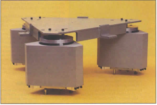
Negative-stiffness-mechanism isolators
offer unsurpassed vibration control
In the 2 to 100-Hz
range.
Vibration is a fact of life in most industrial settings, but
in some applications it cannot be tolerated. When fabricating
microelectronics, machining to extreme tolerances, or using
industrial laser/optical systems, for example, a vibration-free
environment is a must.
Until recently, air springs offered the best vibration isolation.
But newly developed negative-stiffness mechanism (NSM) isolators
control 2 to 100-Hz vibrations 10 to 100 times better than air
springs.
Vertical and horizontal isolators combined in a single package
provide a passive, mechanical 6-DGF (degrees of freedom) isolator.
They are suitable for fixed static loads, applications where
load changes are small, and those where adjustments for load
changes can be made. Among the benefits the devices bring to
a manufacturing environment are:
- Better resolution and accuracy from inspection instruments.
- Higher yield from fabrication equipment because of fewer rejects or rework.
- Greater versatility in locating vibration sensitive equipment, such as on upper floors of a building instead of the basement.
- Require no air or power supply.
- Have no valves to maintain or replace.
- Do not generate heat.
- Cannot contaminate clean rooms with dirty air.
- Offer natural-frequency adjustment independent of load.
- Are all metal; they can be used in hard vacuums, at high temperatures, and in radiation environments.
- Used its passive elements in active systems, give faster
response to load changes and can automatically adjust natural-frequency.
- Negative-stiffness isolators use mechanical components to keep vibrations from sensitive equipment.
The net result is a compact isolator capable of low vertical
and horizontal stiffnesses and high internal structural frequencies.
Vertical-motion isolation
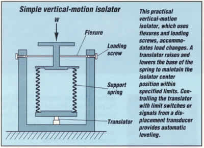
Typical vertical-motion isolators use a conventional spring
to support the pay load and a negative-stiffness mechanism ("snap-through"
or "over-center" mechanism) to cancel some or all
of the spring stiffness. This produces low to zero net vertical
stiffness. The approach has been used successfully to simulate
zero gravity when testing large space structures, for example,
but has not been previously used in 6-DOF isolation systems.
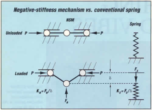 One form of NSM consists
of two bars hinged at the center, supported at their outer
ends on pivots which are free to move horizontally, and
loaded in compression by opposing forces P, When
unloaded, the bars are aligned and in unstable equilibrium
{the center position of the NSM.) When displaced downward
an amount
 ![]() ,
force FN which opposes the
motion holds the center hinge in equilibrium. For small
values of
,
force FN which opposes the
motion holds the center hinge in equilibrium. For small
values of ![]() ,
the ratio between FN and
,
the ratio between FN and ![]() is linear and expressed as the negative stiffness, KN.
The behavior of a conventional spring is also shown, both
unloaded and deflected an amount
is linear and expressed as the negative stiffness, KN.
The behavior of a conventional spring is also shown, both
unloaded and deflected an amount ![]() by the force FS. Here, FS acts in the direction of the displacement
by the force FS. Here, FS acts in the direction of the displacement ![]() to hold the deflected spring in equilibrium. The ratio
of FN to
to hold the deflected spring in equilibrium. The ratio
of FN to ![]() is the positive stiffness KS.
is the positive stiffness KS.
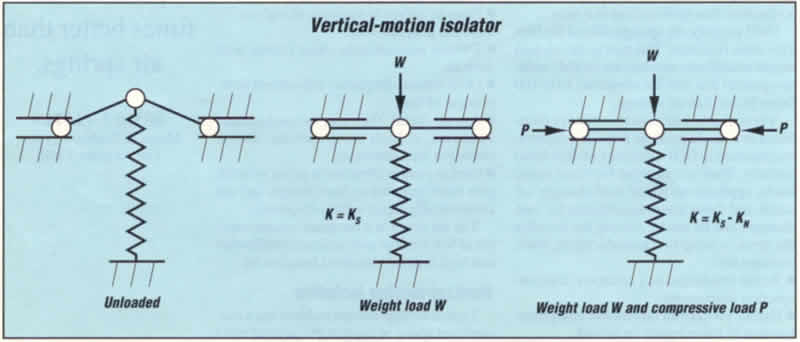
Combining the spring and NSM produces a vertical-motion
isolator. When a load W deflects the spring to
the center position of the isolator, the spring provides
vertical stiffness. Applying forces P to the bars
creates the NSM, which cancels some or all of the spring
stiffness. The resulting isolator stiffness is K= KS-KN,
and can be made to approach zero while the spring still
supports the weight. Flexures used in place of hinged
bars offer advantages in some systems. Loading screws,
piezoelectric devices, and various other means produce
compressive loads.
Horizontal-motion isolation
A set of flexible columns or beam-columns that behave as springs,
combined with NSMs, isolate horizontal motion. This is illustrated
by a payload supported on two flexible columns. A horizontal
force displaces the payload without significant rotation because
the columns are much stiffer vertically than horizontally. Horizontal
stiffness can approach zero by loading the columns near their
critical buckling loads, thereby producing very low natural
frequencies for horizontal vibrations.
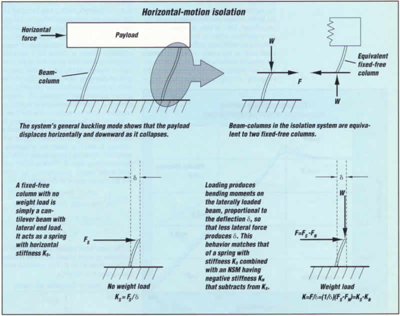
The system's general buckling mode is illustrated by a deformed
shape. As the system collapses the payload moves horizontally
and downward. Adding stops to limit horizontal displacement
produces a system that is fail-safe against collapse due to
inadvertent overload. Limiting horizontal displacements to small
values changes the buckling mode and increases the buckling
strength nominally by a factor of four Of course, the system
does not isolate when the payload hits the stops.
This approach uses the beam-column effect: axial loading reduces
bending stiffness of a beam-column. The beam-columns in the
isolation system shown are equivalent to two fixed-free columns.
For a single fixed-free column with no load weight, the beam-column
is simply a cantilever beam with lateral (horizontal) end load,
and acts as a spring with horizontal stiffness KS.
Load W produces bending moments on the laterally loaded
beam, proportional to the deflection ![]() ,
so that less lateral force produces
,
so that less lateral force produces ![]() .
This behavior matches that of a spring with stiffness KS combined with an NSM having negative stiffness KN that subtracts from KS. As W approaches the critical buckling load. KN approaches KS and the net horizontal
stiffness of the beam-column approaches zero.
.
This behavior matches that of a spring with stiffness KS combined with an NSM having negative stiffness KN that subtracts from KS. As W approaches the critical buckling load. KN approaches KS and the net horizontal
stiffness of the beam-column approaches zero.
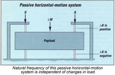
The simple horizontal-motion isolation system shown in the figure
passively accommodates changing weights while maintaining a
fixed isolation-system natural frequency. Two sets of flexible
columns preloaded with axial load Q support the payload.
Each set has an upper and lower column. The lower column supports
part of the weight plus the axial preload; the upper column
supports only the axial preload.
Because of the columns' axial flexibility and other flexibility
in the system, increasing payload weight increases axial load
on the lower column and decreases it on the upper column. This,
in turn, increases the negative-stiffness effect in the lower
column, reducing its horizontal stiffness. Decreasing axial
load on the upper column decreases the negative stillness effect
in the upper column, increasing its horizontal stiffness. By
properly sizing the upper and lower columns, the horizontal
stiffness changes in proportion to changes in payload weight,
so the natural frequency remains unchanged.
Changing the preload Q changes the negative-stiffness
effect in the upper and lower columns in the same direction,
thereby providing an independent means for adjusting the system
horizontal stiffness and resonant frequency.
Damping
Damping limits resonant responses. Reducing stiffness with the
NSM magnifies the inherent system damping, resulting in high
hysteretic damping. High hysteretic damping is more desirable
than high viscous damping because it limits resonant responses
without significantly reducing isolation efficiencies at higher
frequencies.
Transmissibility curves shown for a hysteretically damped system
illustrate this fact. For example, with a loss factor of 1.0,
the resonant transmissibility is 1.4 and transmissibilities
at higher frequencies deviate only slightly from the ideal undamped
curve. For comparison, a transmissibility curve is shown for
a viscously damped system that gives the same resonant transmissibility
of 1.4 (the viscous critical-damping ratio is 0.5). The difference
in transmissibilities between viscously damped and hysteretically
damped systems at higher frequencies is significant considering
the log scale used in the figure.
 Magnifying the damping by reducing the
stiffness with the NSM can be explained as follows. Consider an ordinary spring with stiffness KS and loss factor
 ![]() S,
supporting a mass and vibrating harmonically with displacement
amplitude
S,
supporting a mass and vibrating harmonically with displacement
amplitude ![]() .
The loss factor is related to the energy dissipated
in the spring and the energy stored in the spring by
.
The loss factor is related to the energy dissipated
in the spring and the energy stored in the spring by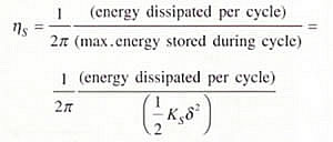
The same basic relationship applies to
the isolation system where an NSM reduces stillness
from KS to K. The
resulting isolation system loss factor is as the NSM reduces net stiffness K, the maximum
elastic energy stored during the cycle, and associated
with
 ![]() ,
decreases, but the energy dissipated per cycle does
not, The energy dissipated per cycle is the energy dissipated
by the spring, and can be expressed by the first equation.
Combining the two equations gives
,
decreases, but the energy dissipated per cycle does
not, The energy dissipated per cycle is the energy dissipated
by the spring, and can be expressed by the first equation.
Combining the two equations gives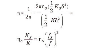 where
where ![]() S is system natural frequency based on the spring stiffness
and
S is system natural frequency based on the spring stiffness
and ![]() is
system natural frequency based on the reduced stiffness.
is
system natural frequency based on the reduced stiffness.
The system's general buckling mode is illustrated by a deformed
shape. As the system collapses the payload moves horizontally
and downward. Adding stops to limit horizontal displacement
produces a system that is fail-safe against collapse due to
inadvertent overload. Limiting horizontal displacements to small
values changes the buckling mode and increases the buckling
strength nominally by a factor of four Of course, the system
does not isolate when the payload hits the stops.
This approach uses the beam-column effect: axial loading reduces
bending stiffness of a beam-column. The beam-columns in the
isolation system shown are equivalent to two fixed-free columns.
For a single fixed-free column with no load weight, the beam-column
is simply a cantilever beam with lateral (horizontal) end load,
and acts as a spring with horizontal stiffness KS.
Load W produces bending moments on the laterally loaded
beam, proportional to the deflection ![]() ,
so that less lateral force produces
,
so that less lateral force produces ![]() .
This behavior matches that of a spring with stiffness KS combined with an NSM having negative stiffness KN that subtracts from KS. As W approaches the critical buckling load. KN approaches KS and the net horizontal
stiffness of the beam-column approaches zero
.
This behavior matches that of a spring with stiffness KS combined with an NSM having negative stiffness KN that subtracts from KS. As W approaches the critical buckling load. KN approaches KS and the net horizontal
stiffness of the beam-column approaches zero
Damping can be greatly magnified in a typical NSM isolation
system. For example, consider a vertical-motion isolation system,
where the spring's frequency is 5 Hz, and the NSM's is 0.5 Hz.
According to the third equation, the isolation system loss factor
equals the spring loss factor multiplied by 100. Therefore,
1% structural damping in the spring produces 100% structural
damping in the isolation system.
Adding damping improves the suspension system, particularly
high-damping viscoelastic materials. Consider a suspension consisting
of a steel spring and viscoelastic damper. The system stiffness
is the sum of the spring and damper stiffnesses, but essentially
all the damping comes from the viscoelastic material. By adding
negative stiffness with an NSM equal to the stiffness of the
steel spring, the resulting suspension behaves dynamically as
though the payload were suspended on only the damper. This approach
produces very low natural frequencies and high damping in compact
systems.
The damping behavior of viscoelastic materials typically falls
between the viscous and the hysteretic curves shown in the transmissibility
graph. Loss factors for some materials exceed 1.0 over certain
ranges of temperature and frequency, and manufacturers can tailor
materials to particular ranges of interest. For example, some
materials have loss factors exceeding 1.0 at room temperature
and the low frequencies of interest for vibration isolation
-0.2 lo 1.5 Hz. Thus, system resonant transmissibilities lower
than 1.4, and transmissibilities at the higher frequencies close
to ideal undamped systems, are possible.
System stiffness can be reduced below that of the damping material
alone, producing system resonant transmissibilities significantly
lower than 1.4. However under these conditions in totally passive
systems, creep instability can occur. By retaining some positive
stiffness from the mechanical suspension, the system is inherently
stable.
The simple horizontal-motion isolation system shown in the figure
passively accommodates changing weights while maintaining a
fixed isolation-system natural frequency. Two sets of flexible
columns preloaded with axial load Q support the payload.
Each set has an upper and lower column. The lower column supports
part of the weight plus the axial preload; the upper column
supports only the axial preload.
Because of the columns' axial flexibility and other flexibility
in the system, increasing payload weight increases axial load
on the lower column and decreases it on the upper column. This,
in turn, increases the negative-stiffness effect in the lower
column, reducing its horizontal stiffness. Decreasing axial
load on the upper column decreases the negative stillness effect
in the upper column, increasing its horizontal stiffness. By
properly sizing the upper and lower columns, the horizontal
stiffness changes in proportion to changes in payload weight,
so the natural frequency remains unchanged.
Changing the preload Q changes the negative-stiffness
effect in the upper and lower columns in the same direction,
thereby providing an independent means for adjusting the system
horizontal stiffness and resonant frequency.
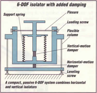 SYSTEM CONFIGURATIONS
Isolators for handling vertical and horizontal
vibrations can be combined to produce various
configurations of 6-DOF isolators.
Passive systems
Compact, passive 6-OOF isolators with added damping
are available with height and width approximately
equal. Size envelopes for this configuration are
comparable to pneumatic isolators that support
the same loads. Other isolators depart radically
from conventional shapes, including low-profile
configurations for use where space is limited.
NSM suspensions arc applicable for a wide range
of loads. For example, a small isolated platform
that supports a microscope and a large system
that support an entire fabrication-room floor
can both give very low frequencies.
Active and automatic leveling systems
An important feature of NSM systems is their capability
for stiffness and frequency control by adjusting
the NSMs. For example, vertical and horizontal-motion
isolators can be combined with a servosystem.
Controlling the vertical-motion translator produces
an automatic leveling system in which the horizontal-motion
natural frequency is insensitive to changes in
payload weight. Likewise, controlling the vertical-motion
NSM makes vertical-motion natural frequency insensitive
to weight changes. As another example, consider
step-and-repeat systems, such as photolithography
machines, with stages that accelerate and decelerate.
Feed-forward control can adjust the NSMs to stiffen
the system during stage acceleration and deceleration
and soften the system during exposures or measurements.
Real-world systems
NSM isolation system behavior closely approaches the transmissibility
curves up to frequencies where the isolator structure itself
resonates. Because the isolators are simple, compact, elastic
structures, their internal-structural resonances arc readily
predictable and can be kept at high frequencies. Isolator resonances
are above 100 Hz in practical 6-DOF systems with isolation system
natural frequencies (frequencies at which the system of payload
and suspension resonates) of 0.2 Hz or lower.
System natural frequencies in the range of 0.5 to 1.5 Hz are
of interest for a wide range of applications, particularly with
low system resonant response, near-hysteretic damping behavior
and isolator internal-structural resonances above 100 Hz. With
high-damping viscoelastic materials, resonant transmissibilities
as low as 1.4 are practical with passive NSM-isolation systems.
Automatic centering systems using an actuator controlled by
signals from displacement or velocity sensors further enhance
performance. Also, because NSM isolators are simple elastic
structures and viscoelastic materials that deform, their isolation
performance does not degrade with micromotions typical of laboratory
floors and fabrication rooms, as with conventional pneumatic
isolators.
 GAUGING PERFORMANCE
NSM-isolator performance between a system's
natural frequency and first internal structural
frequency closely approaches that of a perfect single-DOF
system. Commercially available models have internal
structural frequencies above 100 Hz.
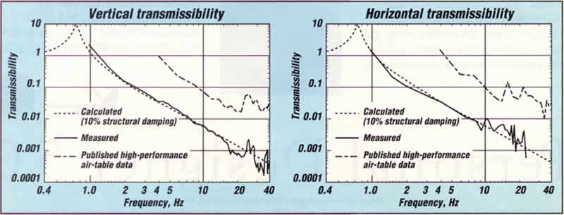
Measured transmissibility versus frequency curves
for a payload supported on three NSM isolators are
shown in the figures. Calculated curves for single-DOF
systems are shown for comparison, as are transmissibility
curves for a high-performance air table, based on
manufacturer's published data.
The measured curves are truncated at the upper frequencies
by signal-to-noise ratios and at the lower frequencies
by transducer frequency-responses.
