Microscopy News - August 2017
Minus K: Negative-Stiffness Vibration Isolation Facilitates Nano-Research into Superionic Solid Electrolytes for Next-Generation Lithium Batteries
Advances in materials testing techniques have enabled scientists and engineers to measure mechanical properties, and observe and characterize mechanical phenomena that control deformation and failure down to nearly the atomic level. One field that is benefiting from such advances in testing techniques is energy storage. The option of creating higher energy capacity batteries has direct implications on performance with laptops, smartphones, and electric vehicles.
Many of the rechargeable batteries used in these portable devices and vehicles are lithium-ion (Li-ion), composed of two electrodes, a positive electrode made of lithium and a negative electrode made of graphite, and a chemical electrolyte. The tremendous capacity of lithium and the metals ability to move lithium ions and electrons in and out of an electrode as it cycles through charge and discharge, make it a well suited anode material.
The electrolyte chemically contains the electric charge and also acts as the medium through which the current flows between electrodes when the battery is connected in a circuit. As the electrolyte in a Li-ion battery also contains a solution of lithium, the lithium electrode tends to react with this medium, causing dendrite fibers to form over the course of battery charge and discharge cycles, particularly when the battery is cycled at a fast rate. These fibers move out from the electrode and into the electrolyte, where they break down the controlled path that the electrons generally take by producing conductive paths haphazardly throughout the structure. This can result in a rapid discharge that allows excess current to flow, causing the battery to fail prematurely. It can also unsafely heat up the battery to a point where it can generate fire.
To realize significant improvements in energy density, vehicle range, cost requirements, and safety, the use of metallic lithium anodes will likely be required for powerful next-generation rechargeable battery chemistries like lithium-air and lithium-sulfur. However, the use of metallic lithium with liquid and polymer electrolytes is limited due to dendrite formation, and efforts to solve this problem have met with limited success.
Researching Pure Lithium and Superionic Solid-State Electrolytes
An alternative approach is being pursued at Michigan Technical University’s Department of Materials Science and Engineering, Small-Scale Mechanical Testing Laboratory, in collaboration with Oak Ridge National Laboratory and the University of Michigan. The research focuses on a pure lithium anode accessed through, and protected by a superionic solid-state electrolyte that would prevent side reactions and enable safe, long-term, and high-rate cycling performance.
“Our lab is focused on the mechanical characterization of small volumes of materials,” saidErik G. Herbert PhD, Assistant Professor, Department of Materials Science and Engineering, Michigan Technical University. “We are trying to understand how materials like metals, ceramics, polymers, composites, and biomaterials respond when their boundaries are mechanically loaded. We perform experiments relating to characteristics such as elasticity and hardness, to probe the properties of these materials.”
“The key risk and current limitation of Li-ion technology is the gradual loss of lithium over the cycle life of the battery,” said Dr. Herbert. “In particular, losses caused by physical isolation from roughening, dendrites or delamination processes, or to chemical isolation from side reactions. To abate these problems we endeavor towards a much deeper analysis of the degradation processes and a predictive understanding of the lithium-metal solid electrolyte interface as a function of cycling.”
“Specifically, we need to understand how the lithium is gradually consumed, why the interfaces are surprisingly resistive, how the electrolyte eventually fails, how defects in the lithium migrate, agglomerate or anneal with further cycling or time,” continued Dr. Herbert. “And additionally, whether softer electrolytes can be used without incursion of lithium dendrites, and what effects processing and fabrication have on the interface performance.”
Among the efforts being pursued to answer these questions, state-of-the-art small-scale mechanical characterization techniques are being carried out at Michigan Technical University to provide the critical information that will directly enable transformative insights into the complex coupling between the microstructure, its defects and the mechanical behavior of both lithium and the solid-state electrolytes.
Nanoindentation Studies
In addition to an extensive array of optical and electron microscopes, atomic force microscopes and x-ray diffraction instruments accessible through the universitys Applied Chemical and Morphological Analysis Laboratory, the Small-Scale Mechanical Testing Laboratory operates a versatile suite of six small-scale mechanical testing platforms in which the user has direct control over the way the test is performed and how the raw data are recorded, reduced, and analyzed.
One of the primary techniques utilized to conduct the Li-ion tests is nanoindentation. Studies of lithium films, various solid electrolytes and completely operational solid-state batteries are being performed in an inert atmosphere as a function of numerous variables, such as strain, strain rate, temperature, chemistry, composition, defect structure, microstructural length scale, and in-operando cycling of the battery.
In a traditional indentation test, macro or micro indentation, a hard tip made of a material such as diamond, whose mechanical properties are known, is pressed into a sample whose properties are unknown. The load placed on the indenter tip is increased as the tip penetrates further into the specimen and soon reaches a defined value. At this point, the load may be held constant for a period of time, or removed. The area of the residual indentation in the sample is measured and the hardness is defined as the maximum load divided by the residual indentation area.
With nanoindentation, small loads and tip sizes are used, so the indentation area may only be a few square micrometers or even nanometers. This presents problems in determining the hardness, as the contact area is not easily found.
Atomic force microscopy or scanning electron microscopy techniques may be utilized to image the nanoscale indentation, but can be cumbersome. Instead, an indenter with a geometry known to have a high precision is employed, such as a Berkovich tip, which is a three-sided pyramid geometry. During the course of the indentation process, a record of the depth of penetration is made, and then the area of the indent under load is determined using analytical models and the known geometry of the indentation tip. A record of the measured parameters can be plotted on a graph to create a load-displacement curve, which is used to extract mechanical properties of the material.
The pivotal nanoindentation system used by the lab is the iNano, manufactured by Nanomechanics, Inc. It is the latest generation of the highest performance ambient and non-ambient nanoindentation systems currently available on the market.
“Among the enabling technology of the iNano is its ability to achieve less than 1 nm of noise in the displacement signal while using a measurement time constant of 20 microseconds,” said Dr. Herbert. “There is no averaging of fast time constant data to lower the noise floor. Coupled with a data acquisition rate of 100 kHz, the critical outcome is that the iNano offers unparalleled ability to perform high-speed testing, and unmatched ability to capture sudden events such as strain bursts, fracture, film delamination, and dynamic ringing.”
“The nanoindentation is mission critical,” continued Dr. Herbert. “Without nanoindentation, there is no way to investigate how the mechanical properties are changing the function of these variables in the solid electrolytes and lithium anodes. We measure such characteristics as the phase angle, which provides a direct measure of the materials damping capability, and gives us an understanding how it dissipates mechanical energy.”
 Negative-Stiffness Vibration Isolation
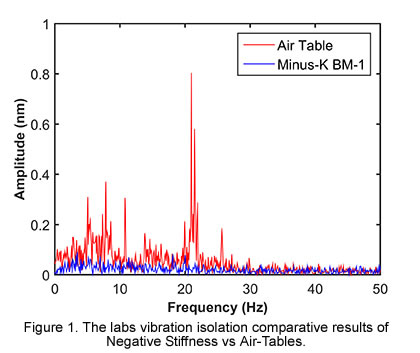
The nanoindentation measurements being performed within the Small-Scale Mechanical Testing Laboratory can range from only a few nanometers in depth, but are typically in the vicinity of 50 to 300 nanometers (0.05 to 0.15 microns) in depth. Measurements at this nano-level of precision require isolation from ambient environmental vibrations, particularly very-low-hertz vibrations, which air tables are incapable of adequately preventing. Isolating a laboratory’s sensitive nano-instrumentation against low-frequency vibrations has become increasingly more vital to maintaining imaging quality and data integrity.
Low-hertz vibrations can be caused by a multitude of factors. Every structure is transmitting noise. Within the building itself, the heating and ventilation system, fans, pumps, and elevators are just some of the mechanical devices that create vibration. Movement of people within the building is another source of vibrations. Depending on how far away the lab equipment is from these vibration sources, and where in the structure the equipment is located, whether on the third floor or in the basement, for example, will determine how strongly the instrumentation will be influenced. External to the building, the labs research can be influenced by vibrations from vehicle movement, nearby construction, noise from aircraft, and even wind and other weather conditions can cause movement of the structure.
 Any high-resolution instrument such as an electron microscope, atomic force microscope, transmission electron microscope, or nanoindentation system, should best be located in a basement on a thick concrete slab or bedrock to minimize the effect of low-hertz vibrations. With highly sensitive instrumentation these vibrations will influence and corrupt data sets and imaging. But locating its precision nanoindentation instruments in the basement was not an option for The Small-Scale Mechanical Testing Laboratory.
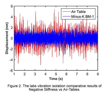
“We set up the lab on the sixth floor of our building, because this location had the best temperature stability, which is required for our research,” said Dr. Herbert. “But we had to contend with low-hertz vibrations from the air handling system which sits above the seventh floor on the roof. The vibrations can actually be felt coming through the building structure. We positioned the iNano indentation system on one of the labs existing air tables, and measured the displacement as a function of time. The noise was just entirely too large to extract meaningful results. If we were going to make use of this location that had the best temperature stability, we needed to find a better vibration isolation solution.”
Having used Negative-Stiffness vibration isolation in the past for laboratory microscopy applications, the lab reached out to Minus K Technology, the developer of Negative-Stiffness isolators, to recommend a solution for the nanoindentation system.
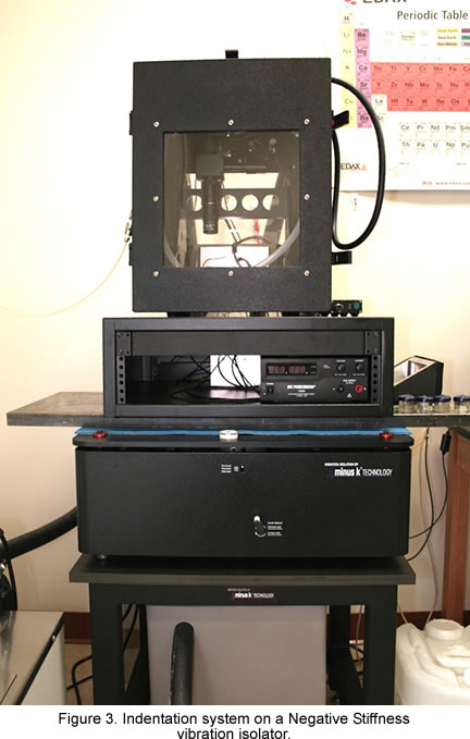
 “We positioned the iNano on a model BM-1 Negative-Stiffness isolator, just as we had done on the air table, and ran the exact same test regimen for several days,” said Dr. Herbert. “The Negative-Stiffness isolator outperformed the air table by a long shot. Looking at the data sets, it is very clear that there is a huge gain from the Negative-Stiffness isolator over the air table.”
What is very advantageous about Negative-Stiffness isolators is that they achieve a high level of isolation in multiple directions. Negative-Stiffness isolators have the flexibility of custom tailoring resonant frequencies to 0.5 Hz* vertically and horizontally (with some versions at 1.5 Hz horizontally).
>“Vertical-motion isolation is provided by a stiff spring that supports a weight load, combined with a Negative-Stiffness mechanism,” said Dr. David Platus, inventor of Negative-Stiffness isolators, and president and founder of Minus K Technology. “The net vertical stiffness is made very low without affecting the static load-supporting capability of the spring. Beam-columns connected in series with the vertical-motion isolator provide horizontal-motion isolation. A beam-column behaves as a spring combined with a negative-stiffness mechanism.”
Vibration transmissibility is a measure of the vibrations that are transmitted through the isolator relative to the input vibrations. Negative-Stiffness isolators, when adjusted to 0.5 Hz, achieve approximately 93 percent isolation efficiency at 2 Hz; 99 percent at 5 Hz; and 99.7 percent at 10 Hz. Negative-Stiffness isolators deliver very high performance, as measured by a transmissibility curve.
Negative-Stiffness isolators resonate at 0.5 Hz. At this frequency there is almost no energy present. It would be very unusual to find a significant vibration at 0.5 Hz. Vibrations with frequencies above 0.7 Hz (where negative-stiffness isolators begin isolating) are rapidly attenuated with increases in frequency.
Expectations
“The expected outcome of our research is a clear interpretation and understanding of how the mechanical properties of a lithium anode and solid electrolyte control ion transport and limit the overall cycling performance of solid-state battery technology,” said Dr. Herbert. “This would reveal the design rules essential for successful fabrication of the solid electrolyte and packaging, in order to maintain full access and efficient cycling of the lithium over many cycles. It would enable the development of advanced Li-ion batteries, capable of considerable expanded performance, and significantly safer than any other Li-ion battery options currently available.”
Added Dr. Herbert, “Without question, both Nanoindentation and Negative-Stiffness vibration isolation have proved absolutely critical to advancing this important Li-ion research.”
(*Note that for an isolation system with a 0.5 Hz natural frequency, isolation begins at 0.7 Hz and improves with increase in the vibration frequency. The natural frequency is more commonly used to describe the system performance.)
|