![]()
SPIE International Society of Optical Engineering - July 1999
Optomechanical
Engineering and Vibration Control
Negative-Stiffness-Mechanism Vibration Isolation
Systems
David L. Platus, Minus K Technology, Inc., 420 S. Hindry
Ave., Unit B, Inglewood, CA 90301
Tel.: 310-348-9656, Fax: 310-348-9638, E-mail: minusk@aol.com
Minus K Technology
11775 Gateway Boulevard, #6, Los Angeles, CA 90064 USA
ABSTRACT
Negative-Stiffness-Mechanism (NSM) vibration
isolation systems offer a unique passive approach for achieving
low vibration environments and isolation against sub-Hertz
vibrations. "Snap-through" or "over-center"
NSM devices are used to reduce the stiffness of elastic
suspensions and create compact six-degree-of-freedom systems
with low natural frequencies. Practical systems with vertical
and horizontal natural frequencies as low as 0.2 to 0.5
Hz provide isolation efficiencies one to two orders of magnitude
better than top-performance air tables and pneumatic isolation
systems. Electro-mechanical auto-adjust mechanisms compensate
for varying weight loads and provide automatic leveling
in multiple-isolator systems, similar to the function of
leveling valves in pneumatic systems. All-metal systems
can be configured which are compatible with high vacuums
and other adverse environments such as high temperatures.
These isolation systems enable vibration-sensitive instruments
such as scanning probe microscopes, micro-hardness testers
and scanning electron microscopes to operate in severe vibration
environments sometimes encountered, for example, on upper
floors of buildings and in clean rooms. Such operation would
not be practical with pneumatic isolation systems. Similarly,
they enable vibration-sensitive instruments to produce better
images and data than those achievable with pneumatic isolators.
The theory of operation of NSM vibration isolation systems
is summarized, some typical systems and applications are
described, and data on measured performance is presented.
KEY WORD LIST
Vibration / Isolation / Isolator / Platform / Suspension
/ Negative-Stiffness / Low-Frequency / Sub-Hertz / Microscopes
/ Micro-hardness.
THEORY OF OPERATION
The theory of NSM isolation systems is
explained in References 1 and 2. It is summarize briefly
for convenience.
 Vertical-Motion
Isolation
Vertical-Motion
Isolation
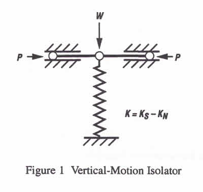
A vertical-motion isolator is shown in Figure 1. It
uses a conventional spring connected to an NSM consisting
of two bars hinged at the center, supported at their
outer ends on pivots, and loaded in compression by
forces P. The spring is compressed by weight W to
the operating position of the isolator, as shown in
Figure 1. The stiffness of the isolator is K=KS-KN where KS is the spring stiffness
and KN is the magnitude of a
negative stiffness which is a function of the length
of the bars and the load P. The isolator stiffness
can be made to approach zero while the spring supports
the weight W.
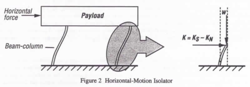
Horizontal-Motion Isolation
A horizontal-motion isolator consisting of two beam-columns
is illustrated in Figure. 2. Each beam-column behaves
like two fixed-free beam columns loaded axially by
a weight load W. Without the weight load the beam-columns
have horizontal stiffness KS With the weight load
the lateral bending stiffness is reduced by the "beam-column"
effect. This behavior is equivalent to a horizontal
spring combined with an NSM so that the horizontal
stiffness is K=KS-KN, and KN is the magnitude of the
beam-column effect. Horizontal stiffness can be nude
to approach zero by loading the beam-columns to approach
their critical buckling load.
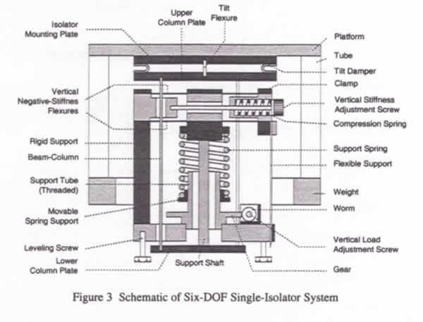
Six-Degree-of-Freedom (six-DOF) Isolation
A six-DOF NSM isolator typically uses three isolators
stacked in series: a tilt-motion isolator on top of
a horizontal-motion isolator on top of a vertical-motion
isolator. Figure 3 shows a schematic of a vibration
isolation system consisting of a weighted platform supported
by a single six-DOF isolator incorporating the isolators
of Figures 1 and 2. Flexures are used in place of the
hinged bars shown in Figure 1. A tilt flexure serves
as the tilt-motion isolator. A vertical-stiffness adjustment
screw is used to adjust the compression force on the
negative-stiffness flexures thereby changing the vertical
stiffness. A vertical load adjustment screw is used
to adjust for varying weight loads by raising or lowering
the base of the support spring to keep the flexures
in their straight, unbent operating position.
Damping
Structural damping inherent in NSM isolators limits the
resonant responses at the natural frequencies. This damping
is magnified by the use of NSMs, as explained in References
1 and 2. The damping magnification can be as high as 100
or greater, limiting the transmissibilities at the natural
frequencies to values below 10. Additional damping is
sometimes provided by the use of elastomeric damping elements,
limiting the transmissibilities at the natural frequencies
to values as low as 2 or 3.
Vertical Auto-Adjustment
One of the shortcomings of low-frequency passive vibration
isolation systems has been their sensitivity to small
changes in weight loads and their susceptibility to large
displacement excursions. This shortcoming has been mitigated
in NSM systems by the use of an electromechanical auto-adjust
mechanism that accommodates variations in weight loads
and maintains the isolators in a precise vertical equilibrium
position. It provides for auto-leveling in multiple-isolator
systems and provides the same function as the leveling
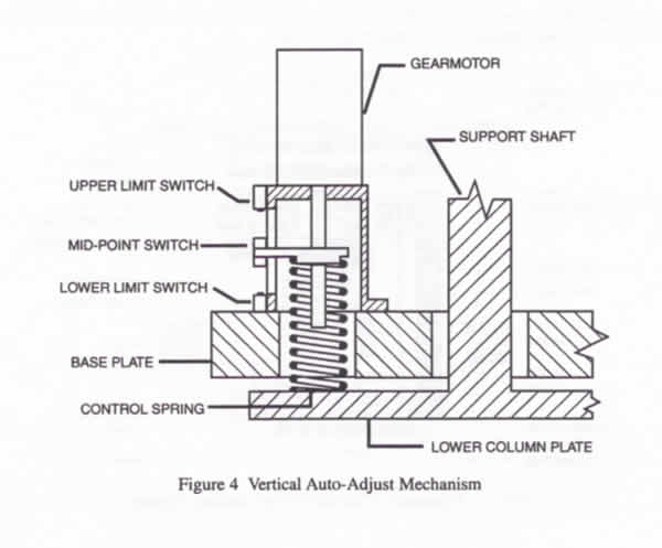
valves in pneumatic vibration isolation systems. A schematic
diagram of an auto-adjust mechanism applicable to the
isolator of Figure 3 is shown in Figure 4, and illustrates
some of the mechanism features.
The auto-adjust mechanism utilizes a pre-compressed control
spring, optical switches (not shown in Figure 4) that
sense changes in vertical position, and a servo-controller.
The control spring adds vertical load to the isolator
by pushing down on the lower column plate. When the vertical
position moves outside a small deadband, the controller
causes a gearmotor to drive a screw that changes the load
on the spring and restores the isolator to its position
within the deadband. A typical load range for the controller
is +/- 2 to 3 Kg to accommodate different specimen weights
in scanning probe microscopes (SPMs) and micro-hardness
testers (MHTs), for example. A manual load-adjustment
screw, such as that illustrated in the isolator of Figure
3, is used to bring the isolator into the range of the
auto-adjust mechanism. A mid-point switch indicates when
the controller is at the middle of its adjustment range
and limit switches indicate when the controller has reached
its adjustment limits.
The buckling mode of the system is also generally indicated by the deformed shape illustrated in Figure 4(a). As the system collapses, the payload displaces horizontally and downward. The addition of stops to limit horizontal displacements produces a system that is fail-safe against collapse due to inadvertent overload. Limiting the horizontal displacements of the payload to small values changes the buckling mode and increases the buckling strength nominally by a factor of four. Of course, the system does not isolate when the payload is against the stops.
TYPICAL APPLICATIONS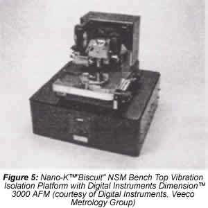
Because of their very high isolation efficiencies, NSM vibration
isolation systems enable vibration-sensitive instruments
such as SPMs, MHTs and scanning electron microscopes (SEMs)
to operate in severe vibration environments that would not
be practical with top-performance air tables or other pneumatic
isolation systems.
Figure 5 shows a Nano-K™* "Biscuit" NSM bench
top vibration isolation platform supporting a Digital Instruments
Dimension™ 3000 AFM. The platform is approximately
600 mm square and 200 mm high. Platforms of this type are
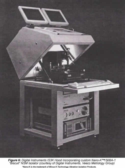
capable of supporting payloads up to 160 Kg or more. Figure
6 shows the Digital Instruments IS3K Hood used with the
Dimension™ 3100 AFM, which includes an acoustic shield
and a custom Nano-K™ "Biscuit" NSM isolator.
This hood allows the Dimension™ 3100 AFM to produce
measurements at the nanometer (lateral) and sub-Angstrom
(vertical) scales in noisy acoustic and vibration environments.
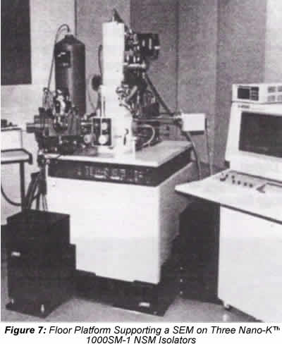
An NSM vibration isolation floor platform for a SEM is shown
in Figure 7. The platform uses three Nano-K™ 1000SM-1
isolators of the type shown schematically in Figure 3, each
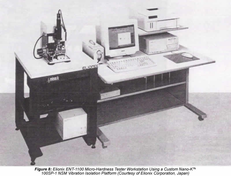
with a payload capacity of about 450 Kg. Figure 8 shows
a workstation for an Elionix ENT-1100 Micro-Hardness Tester
using a custom Nano-K™ 100SP-1 NSM single-isolator
platform of the type shown schematically in Figure 3.
All-metal NSM vibration isolation systems can be configured
which are compatible with high vacuums and other adverse
environments such as high temperatures. Small NSM platforms
similar to that shown schematically in Figure 3, and measuring
about 100 mm high and 150 mm in diameter, have been used
to support scanning tunneling microscopes in ultra-high
vacuums. These platforms have demonstrated vertical and
horizontal natural frequencies as low as 0.5 Hz.
PERFORMANCE
Transmissibility Data
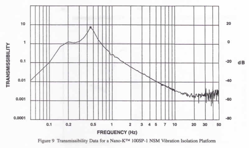
The behavior of NSM vibration isolation systems approximates that of six-DOF linear spring systems up to about 10 to 20 Hz. That is. isolation starts at a frequency of 1.4 times the natural frequency and rolls off at about 12 dB per octave with increasing frequency of the input vibrations. Above 10 to 20 Hz the transmissibility tends toward a constant "floor" value until internal structural resonances are reached. For 0.5-Hz systems this "floor" value is approximately -55 to -60 dB, The internal structural resonances in practical systems can be kept above 70 to 80 Hz or higher, while the system natural frequencies can be kept low. The natural frequencies of NSM isolation systems of the type shown in Figures 5 to 8 can be adjusted, typically, to 0.5 Hz or lower, vertically and horizontally. Some of them can be adjusted to frequencies as low as 0.2 to 0.3 Hz.
Figure 9 shows transmissibility data for a Nano-K™
100SP-1 single-isolator NSM platform of the type shown
schematically in Figure 3, with a natural frequency of
approximately 0.5 Hz. It indicates transmissibilities
of approximately -20 dB at 2 Hz. -40 dB at 5 Hz and -50
dB at 10 Hz.
Comparison of MHT Data Using NSM and Pneumatic Vibration Isolation Systems
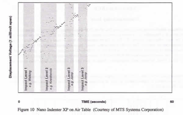
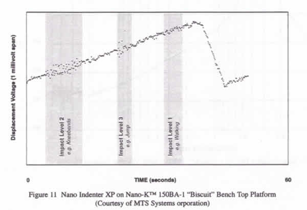
Vibration response of a Nano Indenter XP manufactured by MTS Systems Corporation was compared on an NSM bench top vibration isolation platform and on a on a high-performance air table for severe vibrations produced by impacting the floor. The indenter was set up in a way to maximize its sensitivity to external vibrations. The data are shown in Figures 10 and 11 in terms of displacement voltage vs time.
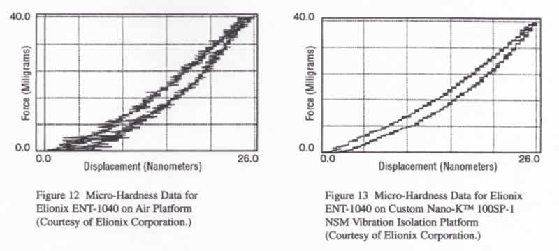
Micro-hardness data for Silicon taken on an Elionix ENT-1040 Ultra Micro-Hardness Tester supported on an air platform and on an NSM platform is shown in Figures 12 and 13.
Based on field test data. NSM vibration isolation systems such as those shown in Figures 5 and 6 typically reduce the vibration noise levels in AFMs by a factor of 2 to 3 or more when compared with top-performance air tables. This is particularly significant for noise levels in the sub-Angstrom range. The use of NSM vibration isolation systems result in clearer images and features not discernable with pneumatic isolation systems. They also enable AFMs to be used in severe environments that would not be practical with pneumatic isolators.
REFERENCES
1. Platus. D. L. "Smoothing out Bad Vibes."
Machine Design. February 26. 1993. p. 123.
2. Platus. D. L.. "Negative-Stiffness-Mechanism
Vibration Isolation Systems. SPIE Vol. 1619 Vibration
Control in Microelectronics. Optics, and Metrology (1991)
pp. 44-54.