![]()
Motion Control Tips - December 2021
Vibration Isolation Technique Supports
Spacecraft Ground Testing
Negative-Stiffness vibration isolation has played an integral role in supporting systems for ground testing and development of spacecraft and components, both inside and outside of vacuum chambers.
December 30, 2021 By Miles Budimir
Steve Varma
Operations Manager
Minus K Technology
Spacecraft ground testing is sensitive to the smallest vibrations, can be caused by a multitude of factors. Every structure is transmitting vibrations from internal and external sources. Within the building itself, the heating and ventilation system, fans, pumps and elevators are just some of the mechanical devices that create vibration. Depending on how far away the testing is from these vibration sources, and where in the structure the testing is being conducted, will determine how strongly the testing will be influenced. External to the building, the testing can be influenced by vibrations from adjacent road traffic, nearby construction, loud noise from aircraft, and even wind and other weather conditions that can cause movement of the structure.
Many of these vibrations are low-hertz, transmitted horizontally. But because horizontal building vibrations are less obvious, they are typically undercompensated for in vibration isolation systems, and consequently transmitted straight through to the testing being conducted.
A solution to this horizontal, low-hertz condition, which has been adopted by hundreds of universities, government laboratories and space agencies engaged in high-precision testing and simulation, is Negative-Stiffness vibration isolation, a patented technology developed by Minus K Technology, Inc.
Negative-Stiffness vibration isolation
Introduced in the mid-1990s, Negative-Stiffness vibration isolation has excelled in vibration-critical applications, largely because of its ability to effectively isolate lower frequencies, both vertically and horizontally.
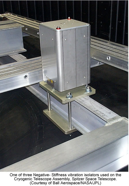
Negative-Stiffness isolators provide a unique capability in vibration isolation, employing a completely mechanical concept with no air or electricity required, and no electronics, motors, or pumps. They operate completely in a passive mechanical mode.
Vertical-motion isolation is provided by a stiff spring that supports a weight load, combined with a negative-stiffness mechanism. The net vertical stiffness is made low without affecting the static load-supporting capability of the spring. Beam-columns connected in series with the vertical-motion isolator provide horizontal-motion isolation. A beam-column behaves as a spring combined with a negative-stiffness mechanism.
These isolators deliver high performance, as measured by a transmissibility curve. Vibration transmissibility is a measure of the vibrations that are transmitted through the isolator relative to the input vibrations. Every isolator will amplify at its resonant frequency, and then start isolating.
Negative-Stiffness isolators typically resonate at 0.5 Hz. Most buildings have little vibration in this region and it would be unusual to find a significant vibration at 0.5 Hz. Vibrations with frequencies above 0.7 Hz are rapidly attenuated with increases in frequency. (Note that for an isolation system with a 0.5 Hz natural frequency, isolation begins at 0.7 Hz and improves with increase in the vibration frequency.) The natural frequency is more commonly used to describe the system performance. When adjusted to 0.5 Hz, Negative-Stiffness isolators achieve approximately 93 percent isolation efficiency at 2 Hz; 99 percent at 5 Hz; and 99.7 percent at 10 Hz.
Some of the isolators provide natural frequencies of 1.5 Hz horizontally and 0.5 Hz vertically; most provide 0.5 Hz vertically and horizontally. Customized Negative-Stiffness isolators can deliver lower natural frequencies both vertically and horizontally. Negative-Stiffness isolators have the flexibility of custom tailoring higher resonant frequencies when lower ones are not required.
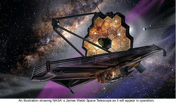
Cryogenic testing of NASA telescope
The vault-like, 40-foot diameter, 40-ton door of NASA’s Johnson Space Center’s historic Chamber A sealed shut on July 10, 2017, signaling the beginning of about 100 days of cryogenic testing for NASA’s James Webb Space Telescope (JWST) in Houston. Behind the hulking door, the process to transform the chamber’s interior to match the airless, frigid environment of space began. It took about 10 days to pull the air from the chamber, and then about one month to lower the temperatures of the Webb telescope and its scientific instruments to the levels required for testing.

The James Webb Space Telescope is the largest cryogenic instrument telescope to be developed for space flight. The final cryogenic test of the Optical Telescope Element (OTE) and Integrated Science Instrument Module (ISIM), as an assembly (OTE + ISIM = OTIS), was performed in the largest super-cold vacuum test chamber of its kind in the world – Chamber A at Johnson Space Center. The temperature of Chamber A was steadily dropped until it reached about 20 kelvins (- 424° F/ – 253° C). This ultimate test of OTIS, the cryogenic portion of JWST, was crucial in verifying the end-to-end performance of JWST.
The telescope is supported by a set of six custom Minus K vibration isolators that use Minus K’s new (patent pending) Thermal Compensator Device.
“This is a passive mechanical device requiring no air or electricity, just like our isolators,” said Dr. David Platus, President of Minus K Technology, and principal inventor of the patented Negative-Stiffness technology. “The Compensator will adjust the isolators as the temperature changes throughout the testing at JSC, keeping the JWST in the proper position.”
In preparation for the Webb telescope’s cryogenic testing, engineers at Johnson suspended it from the ceiling of the center’s Chamber A. This setup consisting of six support rods attached to Minus K Technology’s Negative-Stiffness vibration isolators is meant to isolate the telescope from the vibrations Chamber A could produce once the door closes and testing begins, as well as from disturbances that might occur outside the chamber. The telescope needs an arrangement that holds it and its test equipment in precise relative alignment inside the chamber while isolated from any sources of vibration, such as the flow of nitrogen and helium inside the shroud plumbing and the pulsing of vacuum pumps. The complete range of test equipment includes an interferometer, auto-collimating flat mirrors, and a system of photogrammetry ‘precision surveying’ cameras already used for tests with a surrogate ‘pathfinder’ telescope.
“The system is designed to work in space, where the disturbances are highly controlled and only come from the spacecraft,” said Gary Matthews, an integration and testing engineer at NASA’s Goddard Space Flight Center in Greenbelt, Maryland, who is testing the Webb telescope while it is at Johnson. “On Earth, we have to deal with all the ground-based disturbances, such as the pumps and motors, and even traffic driving by.”
So engineers can keep an eye on the Webb while it is being tested, additional test support equipment including mass spectrometers, infrared cameras and television cameras are also being supported by the vibration isolators.
The James Webb Space Telescope is the scientific successor to NASA’s Hubble Space Telescope. Unlike Hubble’s single monolithic primary mirror, JWST’s primary mirror is made up of 18 individual, adjustable segments that will be aligned in space. The JWST is planned to be launched from Arianespace’s ELA-3 launch complex at European Spaceport located near Kourou, French Guiana in December of 2021 aboard an Ariane 5 launch vehicle. Webb is an international project led by NASA with its partners, the European Space Agency and the Canadian Space Agency.
Vacuum testbed application
Negative-Stiffness vibration isolators have also been used in other NASA applications. For instance, the Spectral Calibration Development Unit (SCDU) is a vacuum testbed built to demonstrate wavelength calibration accuracy and stability between sources of different color and polarization. SCDU was used for the stringent astrometric performance requirements on NASA’s SIM (Space Interferometer Mission)-Lite mission that came from the narrow-angle observing scenario. SIM-Lite was a space-borne stellar interferometer capable of searching for Earth-like exoplanets in the habitable zones of nearby stars.
SCDU was designed to show that the chromatic effect encountered by SIM-Lite could be calibrated to the sub-microarcsecond level. SCDU mostly consisted of a white light interferometer with a metrology system and a real-time control system representative of the science interferometer. It made measurements of external delay differences between pairs of stars. The differences in spectral energy densities between the two stars couple with the instrument optical dispersion and instrument wavefront error to produce a wavelength-dependent delay error.
SCDU successfully demonstrated the calibration of spectral instrument error to an accuracy of better than 20 picometers, which is consistent with the one microarcsecond narrow-angle astrometry. SCDU measured and calibrated simulated spectral sources in the range from 450 to 950 nm. The light sources were intended to simulate the spectral energy differences between F, G and K stars. The testbed used wide-band white light to simulate starlight. The white light source mount required extremely stable pointing accuracy. This was accomplished with the use of Minus K’s Negative-Stiffness vibration isolators under the SCDU testbed. The isolation system consisted of three custom 1,350-pound capacity vacuum-compatible isolators that provided horizontal and vertical natural frequencies of 0.5 Hz.
Minus K Technology
www.minusk.com
|