Spacecraft Ground Testing Vibration Isolation
Systems for ground testing and development of Spacecraft & Components inside or outside of vacuum chambers
Nancy Grace Roman Space Telescope
Ground Testing
of Next-Generation Ultra-Precision Roman Space Telescope Components
The Nancy Grace Roman Space Telescope (Roman), formerly named the Wide Field Infrared Survey Telescope (WFIRST), is a NASA space observatory currently in development and is scheduled to launch into space no later than May 2027.
The Roman Space Telescope will monitor hundreds of millions of stars every 15 minutes for months at a time – something no other space telescope can do. It will detect hundreds of interesting cosmic objects including dwarf planets, rogue planets, brown dwarfs (too massive to be characterized as planets but not quite massive enough to ignite as stars), comets, asteroids and stellar corpses, including neutron stars and black holes, which are left behind when stars exhaust their fuel within our solar system.
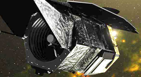
Roman will also survey the birthplaces of stars, giant nurseries of gas and dust which Roman’s large field of view will be able to fully image at high resolution for the first time, completing the exoplanet census begun by NASA's Kepler Space Telescope.
The Roman Space Telescope hosts two instruments: the Wide Field Instrument(WFI) emphasizing studying the evolution of the universe and understanding what solar systems beyond are own are like, and the Coronagraph Instrument to advance technologies for extreme high contrast imaging and spectroscopy from space.
Roman’s primary instrument is the Wide Field Instrument (WFI) which will have a field of view that is 100 times greater than the Hubble widest exposure. It will capture more of the sky with less observing time. Over the first five years of observations, Roman will image over 50 times as much sky as Hubble has covered so far in 30 years. The WFI will measure light from a billion galaxies over the course of the mission lifetime.
Discovering an Earth-like planet with an atmosphere may come down to the ability to block starlight from Roman’s telescope. A coronagraph is an instrument added to a telescope designed to block out the direct light from a star so that nearby objects which otherwise would be hidden in the star's bright glare can be seen.
The main challenge for coronagraphs is controlling starlight, which has a tendency to stray. Just putting a circular mask in front of the star doesn't obstruct the light completely; starlight bends around the mask like ocean waves curving around islands in a process called diffraction.
The Roman Space Telescope includes a Coronagraph Instrument that is a multi-layered and highly complex piece of technology, consisting of a system of masks, prisms, detectors, and two self-flexing mirrors (deformable mirrors). These mirrors are active components, changing their shape in real time to accommodate incoming light to compensate for tiny changes in the telescope’s optics and observatory vibrations.
In tandem with high-tech “masks” and other components – collectively known as “active wavefront control” – these deformable mirrors remove the interference caused by light waves that bend around the edges of the coronagraph’s light-blocking elements. The end result is that starlight is greatly dimmed while faintly glowing objects (that were previously invisible) will appear relatively undimmed.
Changes on the deformable mirrors’ surfaces and active wavefront control are so precise they can compensate for errors smaller than the width of a strand of DNA.
Testing Critical Coronagraph Components
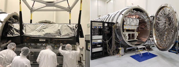
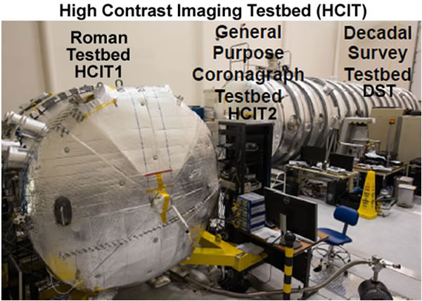
The High-Contrast Imaging Testbed (HCIT) facility at JPL is a large optical laboratory that hosts three optical testbeds inside vacuum chambers designed to advance coronagraph technologies for space.
The Roman testbed is a 6-foot diameter vacuum chamber with a 7.5-foot cylindrical section, and can accommodate tables up to 8 feet in length when accounting for the outward bulge of the end cap doors. Power cables, data cables, water lines, and optical fibers are fed through ports in the sidewalls. Two ports are occupied by camera umbilicals to connect bench-mounted camera enclosures to the lab air, which permit us to use Andor Neos CMOS cameras as science detectors in the chamber despite their lack of vacuum compatibility.
The bench itself is a 6.5ft by 4ft invar optical table placed on three vacuum customized Minus K Technology’s negative-stiffness 500CM-1CV isolator legs to passively isolate the bench from vibrations. These legs have a manual adjustment range that allows them to be retuned to account for changes in weight distribution on the table following hardware modifications.
The Roman vacuum chamber provides a stable and dark environment for experiments while eliminating atmospheric effects. The testbed is heavily instrumented with temperature sensors, as well as a few accelerometers, with contamination monitors planned for the future. The chamber wall temperature is maintained to within +/- 0.1 K using a simple control system. More sophisticated control is used to stabilize the Deformable Mirror (DM) temperature to milli-K levels.
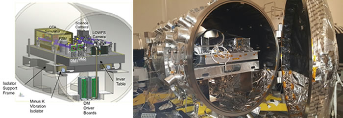
Within Roman, the bench and optical telescope assembly (OTA) sub-bench are on independent PI thermal control loops which stabilize the mean bench temperature to 30mK P-V under normal conditions. The chamber itself is controlled to a set point above laboratory ambient by a PID loop implemented with heater tape under an insulation layer, and can be stabilized to 50mK P-V. All optical mounts were machined from invar with optics bonds within flexure mounts, to minimize the effect of residual thermal fluctuations on the system. The primary heat sources on the table are the two cameras (science and low order wavefront sensing and control, and the DM electronics, and all are cooled by a pair of external water-cooling loops.
The Decadal Survey Testbed (DST) is a new, advanced testbed aimed to demonstrate the coronagraph technologies required for a mission following Roman that will directly image and characterize Earth-like exoplanets that consists of a stellar source simulator, two deformable mirrors (DMs) for wavefront control, coronagraph masks, a wavefront sensor, and an imaging camera. The DST’s opto-mechanical design minimizes disturbances from the laboratory and local environment.
At its foundation, the DST consists of a carbon-fiber optical table that is highly stable to thermal fluctuations. It also includes active temperature control and Minus K’s SM-1CV Negative-Stiffness Vibration isolators customized for use inside the vacuum chamber to reduce the sensitivity to micro seismic and laboratory vibrations.
Another challenge in designing coronagraphs is adjusting for a space telescope's tiny vibrations, or jitter. Telescopes in space experience warping and vibrations that need to be measured and compensated for inside the coronagraph. The team at JPL is assessing how their coronagraphs handle jitter by simulating the effects in a vacuum chamber. They built a table-top-size telescope simulator for the tests that will allow the Coronagraph Instrument testing under realistic space-like conditions.
ICESat-2
Measuring By Space Lasers
Thanks to NASA's Ice, Cloud and land Elevation Satellite2 (ICESat-2), which lifted off in 2018 and began taking detailed global elevation measurements, including over Earth’s frozen regions, researchers have generated a comprehensive portrait of the complexities of ice sheet change and insights into the future of Greenland and Antarctica.
The ICESat-2 measurements, when compared to the measurements taken by the original ICESat from 2003 to 2009, showed that in Antarctica the ice sheet is getting thicker in parts of the continent’s interior, likely as a result of increased snowfall. But the massive loss of ice from the continent’s margins far outweighs any small gains in the interior. In those places, the loss is due to warming from the ocean.
This is one of the first times that researchers have used laser altimetry to measure loss of the floating ice shelves around Antarctica simultaneously with loss of the continent's ice sheet. The researchers found ice shelves are losing mass in West Antarctica, where many of the continent's fastest-moving glaciers are located as well. Patterns of thinning over the ice shelves in West Antarctica show that Thwaites and Crosson ice shelves have thinned the most, an average of about 5 meters (16 feet) and3 meters (10 feet) of ice per year, respectively.
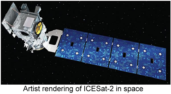
ICESat-2 spacecraft serves as a power and pointing platform for the mission's single instrument, the Advanced Topographic Laser Altimeter System, or ATLAS. It is a space-based LIDAR (Light Detection and Ranging), which measures distances by illuminating a target with a laser and analyzing the reflected light. ATLAS measures the travel time of laser photons from the satellite to Earth and back; computer programs use the travel time from multiple pulses to determine elevation.
“ATLAS required us to develop new technologies to get the measurements needed by scientists to advance the research,” said Doug McLennan, ICESat-2 Project Manager. “That meant we had to engineer a satellite instrument that not only will collect incredibly precise data, but also will collect more than 250 times as many height measurements as its predecessor.”
As it circles Earth from pole to pole, ICESat-2 will measure ice heights along the same path in the polar regions four times a year, providing seasonal and annual monitoring of ice elevation changes. Beyond the poles, ICESat-2 will also measure the height of ocean and land surfaces, including forests.
As ICESat-2 orbits, ATLAS generates six green laser beams arranged in three pairs in order to better determine the surface's slope and provide more ground coverage. Each beam pair is 3.3 km (2.1 mi) apart across the beam track, and each beam in a pair is separated by 2.5 km (1.6 mi) along the beam track. The laser array is rotated 2 degrees from the satellite's ground track so that a beam pair track is separated by about 90 m (300 ft). ATLAS emits visible laser pulses at 532 nm wavelength. Though powerful, the laser is not hot enough to melt ice from its vantage point some 300 miles (500 kilometers) above the Earth.
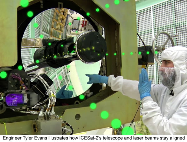
The laser pulse rate combined with satellite speed results in ATLAS taking an elevation measurement every 70 cm, akin to taking 130 images of a single football field. Measurements are taken every 2.3 feet (0.7 meters) along the satellite's ground path.
The laser fires at a rate of 10,000 times a second. Each pulse sends out about 200 trillion photons, almost all of which are dispersed or deflected as the pulse travels to Earth's surface and bounces back to the satellite. About a dozen photons from each pulse return to the instrument and are collected with a 79 cm (2.6 ft) beryllium telescope. The instrument’s filters ensure that only photons with a wavelength of 532 nm are counted, and computer programs further identify photons likely to have come from the laser.
Ensuring ATLAS Can Last
ATLAS went through an initial round of testing in the spring and summer of 2016 at NASA’s Goddard Space Flight Center as it was being assembled. The testing team jolted it on a vibration table, blasted it with sound to simulate a noisy rocket launch, then put it in a vacuum chamber to test it in both extreme heat and extreme cold temperatures.
While ICESat-2 is in orbit, it goes from basking in the heat of the sun to freezing in Earth's shadow every 90 minutes. So before launching the satellite into the harsh environment of space, Goddard engineers wanted to make sure that the laser instrument worked consistently day and night, whatever the temperature.
The vacuum chamber was configured with four vacuum-compatible 800CM-1CV negative-stiffness vibration isolators to support the ATLAS instrument for the thermal vacuum testing. “The Minus K isolators’ primary use was inside the thermal chambers which did not have as stable of a mounting surface as we would have liked,” said Brian Simpson, mechanical lead for ATLAS testing. “The isolators were critical in cancelling out jitter introduced into our system by the facility.”

The ICESat-2 team worked around the clock to test ATLAS in a temperature-controlled vacuum chamber at Goddard, ensuring that its interconnected components worked together and functioned as expected.“When we did these tests, we wanted to confirm that in the worst-case conditions on orbit, both hot and cold, with no air, you still get the expected performance that you want from the instrument," said Melody Djam, system engineer at Goddard. "It's an extreme test."
For the test, engineers calculated how hot the instrument will get on orbit either in full sun or in Earth's shadow – then went 5 degrees Celsius beyond that to cover all bases in a “survival” test. With liquid nitrogen and heaters, the thermal vacuum then cycled four times between 55C and -25C (131F and -13F).
At each of those maximum or minimum temperatures, test engineers sent laser signals through a specially designed fiber optic cable that simulates laser light bouncing off Earth and returning to the spacecraft. The science team had designed different scenarios that reflect light in different ways – a glacier in summer, for example, results in different photon returns than a forest in fall or an ocean under cloudy skies. And the instrument also has to tell the difference between laser photons that it needs to count, and the static of background photons from natural sunlight. Plus, it has to do this under the different temperatures that could cause materials to expand or contract.
Specifically-designed ground support equipment, or test fiber optics and lasers simulated all these scenarios, testing not only how the ATLAS detectors and electronics perform, but how the computer programs that will receive the data on Earth interpreted those returns.
"Because our integration and testing process is so long and involved, and because there are so many electronic interfaces, we really wanted to get most of those electronics together in the thermal vacuum tests to see how they all behaved," said Cathy Richardson, ATLAS instrument project manager at Goddard. "Problems that we might find during testing, we wouldn't have otherwise found for another year. It's a significant risk mitigator for us.”
"We really needed to see how everything plays off each other," Richardson said. "What you care about is the flight hardware working together." And the avionics system performed well, she said, returning data that correlated with what the scientists expected to see.
NASA James Webb Space Telescope (JWST)
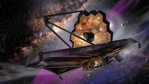
NASA’s James Webb Space Telescope Required Unprecedented Testing of the JWST Before Going To Space.
 All of the JWST systems-level cryogenic vacuum tests were performed at the NASA Johnson Space Center’s (JSC) Chamber-A. Chamber A is now the largest high-vacuum, cryogenic-optical test chamber in the world, and made famous for testing the space capsules for NASA's Apollo mission, with and without the mission crew. It is 55 feet (16.8 meters) in diameter by 90 feet (27.4 meters) tall. The door weighs 40 tons and is opened and closed hydraulically. The air in the chamber weighs 25 tons, when all the air is removed the mass left inside will be the equivalent of half of a staple.
For three years, NASA JSC engineers built and remodeled the chamber’s interior for the temperature needed to test the James Webb Space Telescope. Chamber A was retrofitted with the helium shroud, inboard of the existing liquid-nitrogen shroud and is capable of dropping the chamber’s temperature farther down than ever, which is 11 degrees above absolute zero (11 Kelvin, -439.9 Fahrenheit or -262.1 Celsius).
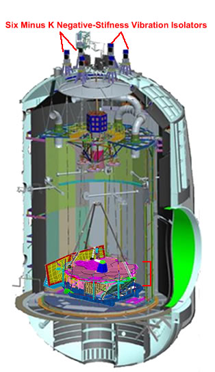
A key addition to Chamber A was the addition of a set of six custom 10,000 lb. capacity Minus K Technology’s negative-stiffness vibration isolators. The Minus K passive isolators do not require air and offer better isolation than air and active isolation systems. A major factor in the selection of the of the vibration isolators was that they not only isolate vibration vertically, but also horizontally at less than 1 Hz.
JWST was designed to work in space where the disturbances are highly controlled and only come from the spacecraft, while on Earth with all the ground-based disturbances, such as the pumps and motors, and even traffic driving by can affect the testing. The Minus K vibration isolators provided dynamic isolation from external vibration sources to create a near flight-like disturbance environment.
The isolators utilize Minus K's patented Thermal Responsive Element (TRE) compensator device, a passive mechanical device, requiring no air or electricity just like the isolators. The TRE compensator adjusted the isolators as the temperature changes throughout the testing at JSC, keeping the JWST in the proper position.
The Critical Design Review for Spacecraft-to-Optical Telescope Element vibration isolation system was completed one month earlier than scheduled at the end of 2011. The six Minus K negative-stiffness vibration isolators were installed on top of Johnson Space Center’s Thermal Vacuum Chamber A in March 2014.
JWST needed a support structure inside the vacuum chamber to hold equipment for the testing. Engineers installed a massive steel platform suspended from the six vibration isolators via steel rods about 60 feet long (18.2 meters) each and about 1.5 inches (or 38.1 mm) in diameter, to hold the telescope and key pieces of test equipment. The sophisticated optical telescope test equipment included an interferometer, auto-collimating flat mirrors, and a system of photogrammetry ‘precision surveying’ cameras in precise relative alignment inside the chamber while isolated from any sources of vibration, such as the flow of nitrogen and helium inside the shroud plumbing and the rhythmic pulsing of vacuum pumps.
So the engineers could keep an eye on JWST while being tested, additional test support equipment including mass spectrometers, infrared cameras and television cameras were also connected to the support structure that was being suspended and isolation from vibrations by the Minus K negative-stiffness isolators.
The 93-day final test of the fully assembled JWST Optical Telescope Elements and Integrated Science Instrument Module (OTIS) started in July 2017. It took about 10 days to pull the air from the chamber, and then about one month to lower the temperatures of the Webb telescope and its scientific instruments to the levels required for testing. These tests included an important alignment check of JWST’s 18 primary mirror segments, to make sure all of the gold-plated, hexagonal segments acted like a single, monolithic mirror. This required all 132 hexapod actuators to be tested for 6 degrees of freedom (DOF) and radius of curvature for each mirror segment. This was the first time the telescope’s optics and its instruments were tested together.
It was a long and complicated testing process to test JWST. The conditions it will encounter within the cold vacuum of space were simulated on the ground, ensuring the optics and instruments will perform perfectly after launch. This testing was very necessary since JWST will be close to a million miles away from Earth orbiting at L2. This will be too far away for repairs to be made as were done with the Hubble Space telescope.
After more than two decades of development, on Christmas day 2021, NASA launched the James Web Space Telescope (JWST) from French Guiana on South America's northeast coast.
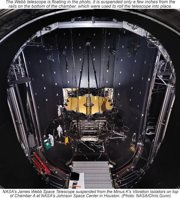
The Pathfinder is a non-flight replica of the Webb telescope’s center section backplane, or “backbone,” that includes flight spare mirrors. The first and second cryogenic optical testing of the Pathfinder were conducted in Chamber A at NASA's Johnson Space Center in Houston, Texas, where the testing of the flight hardware will occur in 2017. "Now that the second test is done, it means that all optical test systems have been checked out," said Lee Feinberg, Webb telescope Optical Telescope Element Manager at NASA Goddard.
Dynamics testing will confirm the telescope and science instrument systems will perform properly together in the cold temperatures of space. So engineers can keep an eye on the Webb while it's being tested, additional test support equipment including mass spectrometers, infrared cameras and television cameras are also being supported by the Minus K’s vibration isolators.
The optical test equipment developed and installed by Harris (formerly ITT Exelis) in the Johnson Space Center (JSC) Chamber A, are “Working out great" said KJ Dziak, Harris Primary Analyst ,“The isolators are down to their 0.5 Hz normal behavior.” After recent adjustments with the assistance of Minus K, the isolators provided an improvement in vibration reduction on the two primary mirror segments of Pathfinder under test.

NASA Lunar Atmosphere and Dust Environment Explorer (LADEE)
NASA's Lunar Atmosphere and Dust Environment Explorer (LADEE), pronounced "laddie,” was a robotic mission launched in 2013 that orbited the Moon to gather detailed information about the structure and composition of the thin lunar atmosphere and the first-ever Lunar Laser Communications Demonstration (LLCD). The LLCD will used lasers, not radio waves, like other spacecraft that have flown beyond close-Earth orbit have used, to communicate with controllers on Earth allowing the spacecraft to communicate at broadband speeds with the ground
Line of Site Jitter Testing
For laser communications systems, maintaining dynamic stability of the laser beam is critical to maintain high data rates. Common design requirements are 1/10 to 1/5 of the angular extent of the beam. For the Lunar Lasercomm Space Terminal (LLST) system, the requirement was 4.2 μrad RMS, which is very small and challenging to meet. Much time was spent modeling and testing this performance metric to ensure the system could meet it. This required the Magneto-hydrodynamic Inertial Reference Unit (MIRU) that provided the active stabilization of the optical telescope to support the fine pointing of the laser during operation in space to be tested for Line Of Site (LOS) jitter.
A detailed finite element model was developed to include all major components of the Optical Module assembly. The purpose of this system model was to capture the structural dynamics behavior of both the overall system, and each of the individual optical elements and to predict the performance of the system.
The model accounted for the structural dynamics of the system, as well as the active stabilization control. The LOS jitter prediction was generated by integrating the results of the optical, structural and controls models.
A test bed was developed to measure the jitter from prototype and flight hardware. For initial jitter testing, a telescope mass mock-up was constructed to mount to a real panel gimbal and flexure. The mass mock-up was designed to closely imitate the mass and moment of inertia of the actual optical head. The panel was mounted to a stiff frame which was mounted to a Minus K BM-4 negative-stiffness vibration isolation table.
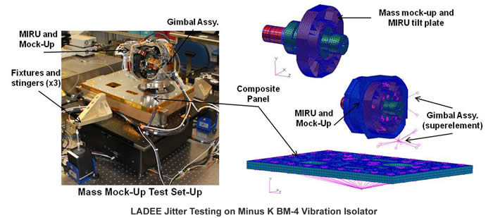
Testing could not be performed with flight conditions, requiring a system model to verify the ability of the optical module to meet the jitter requirements. The model had to be well correlated to the test data, especially in the frequencies that contributed most toward the residual LOS jitter.
Test equipment limitations prevented the hardware from being driven with simultaneous 6-axis input spectrum that was defined for the system. Three stingers were used to excite the Minus K table, and angle rate sensors on the stiff frame were used to measure the input into the panel. Instead, the system could be excited in several, but not all, axes simultaneously.
The data gathered from this testing was used to validate the LOS jitter Finite Element Model (FEM) via direct laser pointing comparisons. The first step in validating the model was to build a FEM that was representative of the hardware being tested, and of the excitation method. The next step was to match the modal frequencies and mode shapes from the test to the FEM.
The first pass at model correlation showed a 25% difference in frequencies from test to FEM predictions at the modes of interest, where ideally there would be no more than 5%. The bolt stiffnesses were modified until FEM predictions from the configurations were within 5% of the measured values.
Simplifying the models further verified that not only did the modal frequencies match, but the mode shapes matched the test data as well. Even after all these modifications the LOS Jitter FEM still did not result in good correlation with the test data.
To finally get the LOS Jitter FEM to agree with the test data, the mass of the fixturing (stiff frame, Minus K table, etc.) had to be included. Additionally, the model had to be loaded with the same 3-point force excitation as the test. By including all these elements, the LOS Jitter FEM finally showed correlation within 5% of test data for the first 4 modes.

LLCD demonstrated error-free communication from the Moon under all conditions, including during broad daylight and even when the Moon was within 3° of the sun, as seen from Earth. LLCD also operated error-free when the Moon was less than 5° above the horizon, as seen from the ground station, which showed that wind and atmospheric turbulence did not significantly impact the system. LLCD was even able to communicate through thin cirrus clouds.
The LLCD used a pulsed laser beam to transmit data over the 239,000 miles from the Moon to Earth at a record-breaking data-download speed of 622 megabits per second (Mbps), over 75 megabytes per second. This download speed was more than six times faster than the speed achieved by the best radio system ever flown to the Moon and would normally take several days to download.
LLCD also demonstrated a 20 Mbps uplink, which was used to loop back error-free high-definition video to and from the Moon, important for future human exploration missions, and also provided simultaneous centimeter-class precision ranging to the spacecraft, which can be used to improve the gravity models of planetary bodies.
In addition to this lack of error, the LLCD was able to switch from one ground station to the next as the Earth turned in a manner that NASA compared to how a mobile phone network operates, and the system did so without human intervention. The system could even lock on to the ground stations without using a radio signal.
NASA/JPL Space Interferometer Mission System Testbed-3 :
The Space Interferometry Mission (SIM) flight vehicle was to be a surveying instrument of unprecedented precision. It was to allow the measurement of stellar positions to a relative accuracy of micro-arc-seconds. This accuracy was to be achieved over a baseline of ten meters between the light collecting siderostat mirrors. This requires measuring distances to the target star to accuracies on the order of 50 pico-meters.
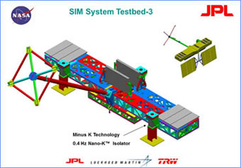
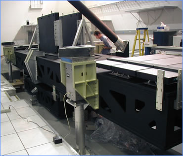
The SIM System Test Bed 3 (STB3) was built to verify that the vibration isolation and active optics systems will work together to achieve the dynamic stability goals.
 |
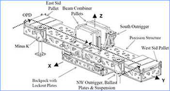 |
A dual stage passive isolation approach was proposed to use isolation first at the vibration-inducing reaction wheels, and a second isolation layer between the bus portion of the space vehicle the backpack) and the optical payload.
The dual stage isolation approach was demonstrated on a dynamically feature-rich, 7-meter structural testbed (STB3). A new passive suspension that mitigates ground vibrations above 0.4 Hz had been integrated into the testbed.
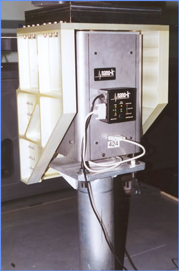
The STB3 suspension utilized Minus K's Nano-K mechanical vibration isolators manufactured by Minus K Technology (formerly sold under the trade name Nano-K). Three isolators were placed beneath outriggers from the structure slightly above and symmetrically around the structure’s mass center in a horizontal plane to ensure stability. The system's natural frequency was 0.4 Hz, vertically and horizontally.
The Minus K isolators utilized negative-stiffness mechanisms to negate the stiffness of conventional support springs, producing the low vertical stiffness. An optical-mechanical servo system maintains vertical position within a +/- 0.010-inch deadband by adjusting the force on a small control spring. The servo system is designed to handle small load changes, temperature changes and long term creep of the support springs.
 |
 |
Transmissibility measurements were conducted for the full STB3 structure in order to determine if the stability goals are being met and the NASA Inventions and Contributions Board awarded a NASA Tech Brief Award to Minus K for their contribution on "Dual Stage Passive Vibration Isolation for Optical Interferometer Missions."
Ball Aerospace & NASA/JPL Spitzer Space Telescope's Cryogenic Telescope Assembly (CTA) :
The Spitzer Space Telescope was a part of NASA's Great Observatories Program and was used to study objects deep within our Solar System and beyond. It first launched in 2003 and completed its hot missions in 2009. The Spitzer Space Telescope used infrared light to obtain images and spectra by detecting the infrared energy, or heat, radiated by objects in space between wavelengths of 3 and 180 microns. The Spitzer Space Telescope captured those celestial objects and phenomena that are too dim, distant or cool to study by other astronomical techniques.
 |
 |
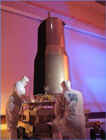
The Spitzer Space Telescope (SST) project concluded early in the program that an end-to-end optical and thermal performance test condition under flightlike thermal conditions would be required to assure that the Cryogenic Telescope Assembly (CTA), which contained the telescope and a superfluid helium cryostat would meet the level-one performance specifications in flight.
The series of end-to-end tests on the CTA while operating at temperatures near absolute zero were conducted at Ball Aerospace's Boulder Colorado large thermal vacuum test chamber nicknamed 'Brutus'.
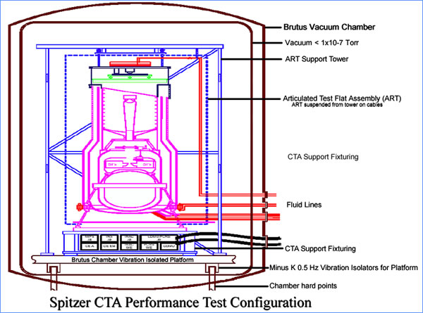
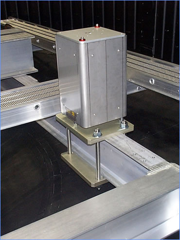
Ball Aerospace selected Minus K's 0.5 Hz vacuum-compatible negative-stiffness vibration isolation system because of the test chamber's horizontal low-frequency vibrations at about 4.5 Hz. The Minus K isolation system consisted of three custom 1000 lb capacity vacuum compatible isolators that provided a horizontal natural frequency of 0.5 Hz.
Materials were selected to meet a vacuum level of about 10-7 torr. The isolators were thermally isolated and heated so they did not have to withstand the temperature extremes of the test. With the use of Minus K's vibration isolators, the jitter in the focus mechanism, a critical parameter for the CTA, was shown to be well within the requirements.
NASA/JPL SIM Interferometer Testbed Spectral Calibration Development Unit (SCDU) :
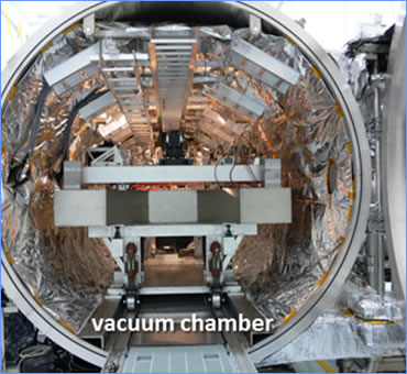
The Spectral Calibration Development Unit (SCDU) was built to demonstrate wavelength calibration accuracy and stability between sources of different color and polarization. SCDU was used for the stringent astrometric performance requirements on NASA's SIM (Space Interferometer Mission)-Lite mission that came from the Narrow-Angle (NA) observing scenario. SIM-Lite was a space-borne stellar interferometer capable of searching for Earth-like exoplanets in the habitable zones of nearby stars.
SCDU was designed to show that the chromatic effect encountered by SIM-Lite and could be calibrated to the sub-microarcsecond level. SCDU mostly consisted of a white light interferometer with a metrology system and a real-time control system representative of the science interferometer. SCDU came online in 2006 and produced its first results in 2007.
 |
 |
The Spectral Calibration Development Unit (SCDU) SIM Lite made measurements of external delay differences between pairs of stars. The differences in spectral energy densities between the two stars couple with the instrument optical dispersion and instrument wavefront error to produce a wavelength dependent delay error. The source of the instrument optical dispersion was the differential material dispersion between the optics of the two arms while the instrument wavefront error results from the differential wavefront error between the two arms.
SCDU successfully demonstrated the calibration of spectral instrument error to an accuracy of better than 20 picometers. This performance is consistent with the one micro-arc second narrow angle astrometry. SCDU measured and calibrated simulated spectral sources in the range from 450 to 950 nm. The light sources are intended to simulate the spectral energy differences between F, G and K stars.
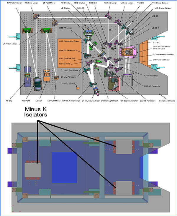
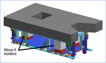
For the Space Interferometry Mission (SIM) the SCDU testbed used wideband white light to simulate starlight. The white light source mount required extremely stable pointing accuracy. This was accomplished with the use of Minus K's negative-stiffness vibration isolators under the SCDU testbed. The Minus K isolation system consisted of three custom 1350 lb capacity vacuum compatible isolators that provided horizontal and vertical natural frequencies of 0.5 Hz.
|
